Description
The cement grout filling between the panels and the fiber-reinforced concrete leveling slab was executed poorly, resulting in an incomplete connection between the panels and the slab. Under the load of passing train compositions, the panels and the rails embedded in them flex until they touch the concrete slab. This creates a spring effect on the railway track and generates shear stresses in the rails in the area between the panels.
A secondary effect is the pumping of water from the drainage ditches parallel to the track, mixed with soil. This pumping is accompanied by the formation of fountains through the technological openings in the panels. It was found that, in addition to the gap between the panels and the concrete leveling slab, there were also poorly compacted or loosened water-saturated sections in the soil foundation, from which muddy mass was being pumped onto the panels.
Task:
To eliminate the described defects and allow the railway track to operate under its design parameters, it is necessary to ensure the proper transmission of the load from the panels onto the concrete leveling slab and through it to the ground foundation.
The voids between the panels and the leveling slab must be filled, and the foundation beneath it must be stabilized.
Conditions and Constraints:
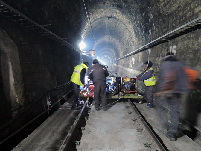
A key requirement was that the railway track remained in operation during the repair work. For the duration of the project, railway traffic was reorganized, with 5-hour windows allocated during daylight hours when no trains passed through the section.
Given this restriction, a technology and materials were chosen that would allow the work to be carried out efficiently, ensuring that the structure of the railway track could withstand the loads of passing trains immediately after the intervention.
Survey of Site Conditions and Void Mapping:
The idea of using ground-penetrating radar (GPR) to determine the areas with loosened soil foundation (embankment, subsoil) was deemed impractical due to the dense reinforcement within the panels, which prevented obtaining interpretable results.
Identification of these zones was carried out based on traces of muddy fountains on the surface of the panels and through direct observations under the load of passing trains.
The voids between the rail panels and the reinforced concrete slab were determined visually and by injecting water through a system of openings. The method relied on the detection of connected cavities and resistance to injection or by using compressed air.
Development of a Technological Scheme, Material Selection, and Scheduling:
Considering the limited work time, tunnel length, logistical specifics, accessibility conditions, and low temperatures, a technological scheme was developed to optimize the process and determine the amount of material that could be successfully injected within a 5-hour window.
Based on the void mapping, a drilling scheme for injection holes (Ø 18 mm) was created, penetrating through the panels and, where necessary, through both the panels and the slab to reach the foundation.
To optimize the workflow, it was decided that all holes would be pre-drilled according to the established scheme.
The installation of injection packers was also carried out in advance, ensuring they would not interfere with railway traffic or be damaged by passing trains. This preparation significantly streamlined the injection process, allowing sufficient attention to be given to proper installation, as errors could not be corrected post-factum.
Equipment and Materials Used:
- A platform for housing the injection equipment and materials
- Air compressor
- Generator
- Two-component injection machine
- Drilling machine – rotary hammer
- Injection packers
- Thermal insulation jackets, tailored to the size and shape of the injection resin containers
- Two-component urea-silicate injection resin, achieving strength within 2 hours of application
- Leveling device
- Lath
This efficient and precisely planned approach ensured the railway track's structural stability while keeping traffic operational throughout the project.